Ceramic Inlay Pcb

Advantage And Applications Of Copper Inlay Pcb In 2020 Circuit Board Electronic Circuit Board Pcb Board

The Advantages And Disadvantages Of Ceramic Multilayer Pcbs Tempo

Https Www Facebook Com Photo Php Fbid 1515756288537599 Set Pcb 1515756435204251 Type 3 Theater Ceramic Techniques Ceramics Bowl
Ceramic Substrates Pcb Board Al2o3 Base Material Ceramic Thermal Management Pcb
Professional Pcb Printed Circuit Board And Electronic Pcb Board

Https Www Facebook Com 4ceramics Photos Pcb 444983675903377 1273259802779209 Type 3 Theater Ceramic Pottery Pottery Ceramics
In each case the exact value depends of course on the ambient con ditions and the admissible power loss.
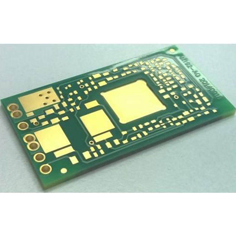
Ceramic inlay pcb.

Aluminum Nitride Pcb Aln Pcb Cercuits Online Ceramic Pcb
High Quality Ceramic Pcb Manufacturer Pwb Fabrication Supplier

Skip Microvia Pcb Supplier Microvia Pcb Manufacturing Rocket Pcb

Backplane Pcb Manufacturer Sequential Lamination Technology Quote

Professional Large Format Pcb Flex Pcb Material Manufacturer

Find Cavity Pcb And Small Pcb Board From Rocket Pcb Solution

Oem Embedded Components Pcb Manufacturer Embedded Pcb

Professional Manufacturing Of Cavity Pcb From Rocket

Press Fit Coin Embedded Pcb Manufacturer Embedded Pcb Maker

Power Pcb Custom Pcb Board Manufacturers From Pcb Solution

Pcb Led Flower Led Flower Flowers Led
Best Printed Board Assembly Printed Circuit Board Fabrication

Cavity Pcb Supplier Cavity Printed Circuit Boards Manufacturing

Perf And Pcb Effects Layouts Sprinkle Drive Diy Guitar Pedal Guitar Pedals Sprinkles

Multi Layer Pcb Manufacturing Process Free Sample Mircovias At Discount Rocket Pcb

Dz65 Rgb V2 Hot Swap Rgb Pcb In 2020 Rgb Led Things To Sell Swap

Vippo Pcb Customization Pofv Pcb Manufacturer Rocket Pcb
Find High Speed Pcb Design Open Cavity Pcb Board Manufacturer
Manufacturer Of Any Layer Pcb And Pcb Board Design

Gold Plated Circuit Board Gold Plated Pcb Board Manufacture
Big Pcb Large Scale Size Pcb Manufacturing On Rocket Pcb

Multicavity Cavity Pcb Pcb Cavity Rocket Pcb

Long Short Gold Finger Pcb Supplier Staged Gold Finger Pcb

Aleph T Aleph Thermion Class A Tube Mosfet Single Ended Amplifier Pcb Circuits Class Electronic Schematics Amplifier
Source : pinterest.com
